D Flip Flop Exitation:
The excitation table of the D flip-flop is generated from its truth table. The excitation table is built in the same way as the SR flip-flop.
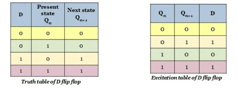
The following state output is equivalent to input D as shown in the truth table below. As a result, creating a wake table is a piece of cake.
D(Data) is the state of the D flip-input flop. Q and Q' reflect the states of the flip-output flop. According to the table, the output changes its state depending on the inputs. The crucial thing to remember is that all this can only happen in the presence of a clock signal. For auxiliary inputs only, it works exactly like an SR flip-flop.
Regardless of the value of Qn, the drive input required for the state transition from Qn = 0 to D = 0 is D = 0 . The input required to trigger the transition from Qn = 0 to Qn+1 = 1 is D = 1.
For input D = 0, the state moves from Qn = 0to Qn+1 = 0 . When D = 1 , the state transitions from Qn = 1 to Qn+1 = 1 .
To obtain the excitation table, all the above state transitions for the D flip-flop from the current state (Qn) to the next state (Qn+1) for the respective excitation inputs are entered into the table.