Finite State Machines using D Flip Flops (FSM using DFF):
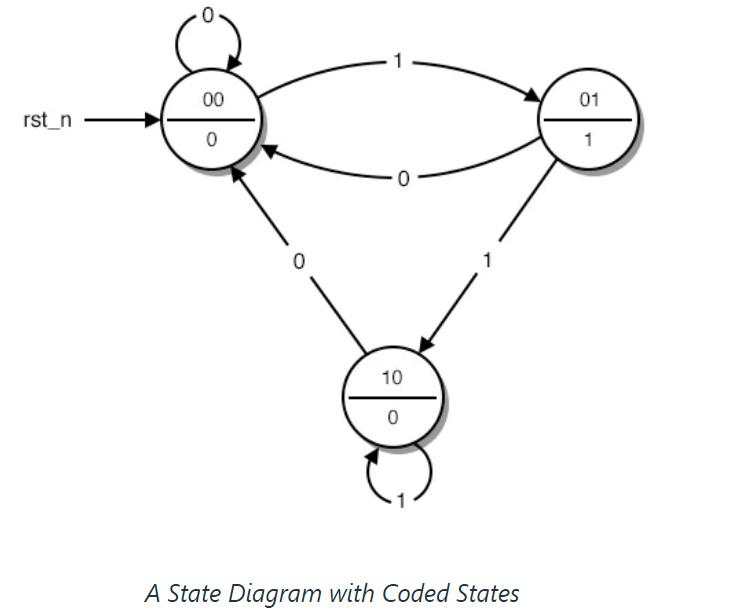
This is a circle and arrow diagram that graphically represents how our circuit works. This figure, which represents the operation of our sequential circuit, is known in mathematics as a finite state machine. Please note that this is a finite Moore machine. Its output is determined only by its current state, not by its input.
Let's explaing state machines with a button example. Where our circuit contains one button, and depending on the press type, we move through the state machine.
We have one output which will turn HIGH when we press the button.

- The first circle represents the "standby" state. This is where our circuit starts and waits for the next button press.
- The second circle represents the situation where the button has just been pressed and our circuit must send a HIGH pulse.
- The third circle represents the circumstance where our circuit waits for the button to be released before returning to the "standby" state.
Next we replace the state name with binary numbers:
State Tabe:
And here we fill the states numbers in A and B, and we check what is the next state depending on every state of the button input I
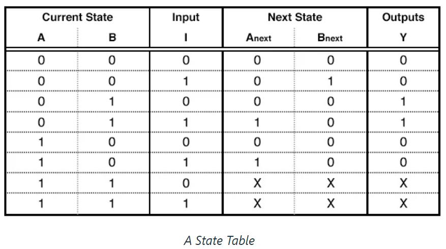
For example:
If we are in state 00 , and our button is at 0, meaning not pressed,
Then our next state will be also 00 and the output will be 0.
If we are in state 01 and the button is HIGH meaning pressed, then our next state will be 01 and our ouutput will also be HGIH.
So we observe our state machine and fill the table.