PLC Ladder Logic Tutorial - Motor Control
In this Tutorial we will learn Ladder Logic Programming by giving an Example on Ladder Motor Control.
Ladder Diagram Symbols used:
NO:
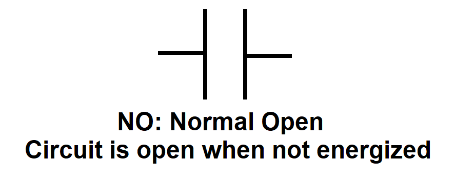
Normal-Open Contacts in Ladder Logic Diagram are used for Buttons, and Actuoator Auxiliary Contacts.
Usually They Cut the circuit Path and prevent signal from passing until they are activated or pressed. For Example, Pressing a button.
NC:
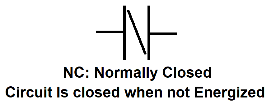
Normal-Close Contacts in Ladder Logic Diagram are also used for Buttons, and Actuoator Auxiliary Contacts.
Usually They Close the circuit and pass signals until they are activated. They cut the path with activation. For Example, Stop Buttons, Fault Contacts and Emergency Stops.
Coil:
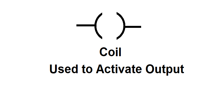
Coil in Ladder Logic Diagram are used to activate an Output. For example, activate a relay, or a contactor coil.
Coil Set:
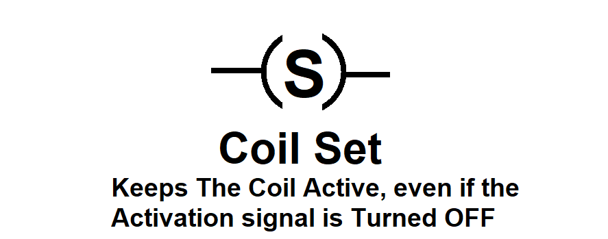
Coil Set in Ladder Logic Diagram are used to activate an Output. But the output will keep active even if the signal that activated has turned OFF. Coil Set can be only turned OFF by a Coil Reset.
Coil Reset:
Coil Reset in Ladder Logic Diagram are used to deactivate an Output that was previously activated by Coil Set.
Motor Control Step By Step using Ladder Diagram
Used Hardware:
- Start Button: To start the Motor Operation.
- Stop Button: To stop the motor Operation.
- Emergency Stop: Usually connected all motors, when pressed, all motors will shut down. Used for emergency situations and is placed sometime in different places around the machine or factory.
- Overload Fault: Overload in Ladder Diagram is a signal that comes from Overload devices, which cuts power when extra current or tempreature pases through the motor cables. Hence it shuts down the motor to protect it.
Motor Control Design in Ladder Logic:
Step 1:

The Start Button is connected to the Motor Set Coil.
If MotorStartButton is Activated, The MotorCoil will be activated hence turning ON the motor.
Step 2:
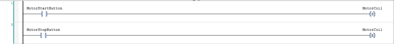
Motor Stop Button is connected to Motor Reset Coil.
If MotorStopButton is Activated, The MotorCoil will be deactivated, turning OFF the motor.
Step 3:
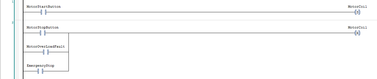
The same way the MotorStopButton is connected to Motor Reset Coil, both. EmergencyStop, MotorOverloadFault could be connected the same way.
Because all of them do the same purpose which is reseting the Motor Coil hence turning OFF the motor.
If MotorStopButton is Activated, The MotorCoil will be deactivated, turning OFF the motor.
Serial Parallel Connection in PLC step by step:
There are two ways to connect Signals in Ladder Logic Diagram called Serial and Parallel.
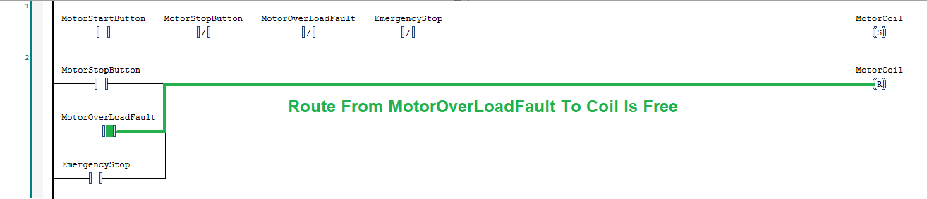
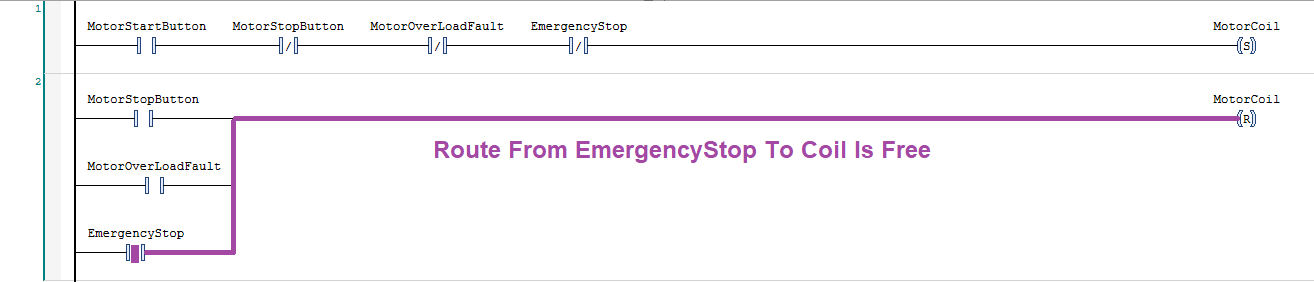
Parallel Lader Logic Diagram:
As you can see we have connected multipe Signals to Motor Reset Coil.
This connection Topology is called Ladder Diagram Parallel Connection.
It is called parallel, because If ANY signal is active, it will lead to triggering Motor Reset Coil.
Take a look:
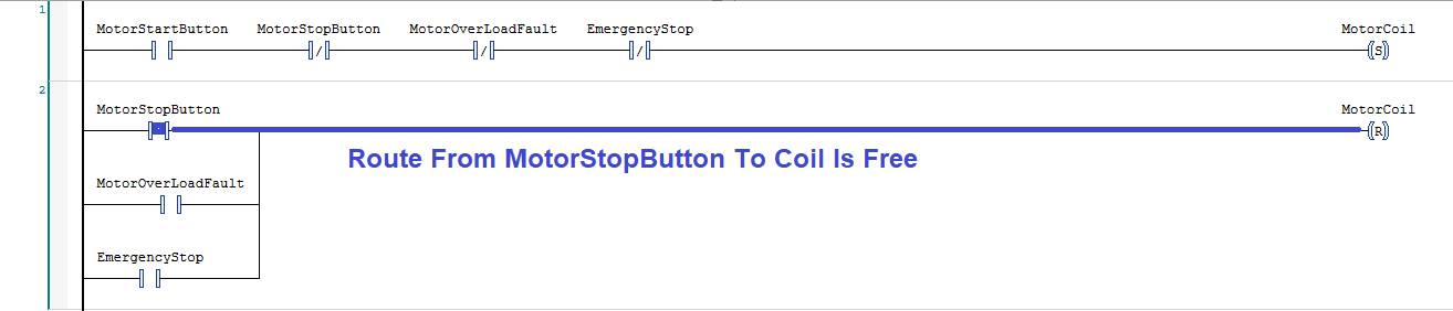
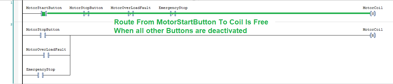
Serial Lader Logic Diagram:
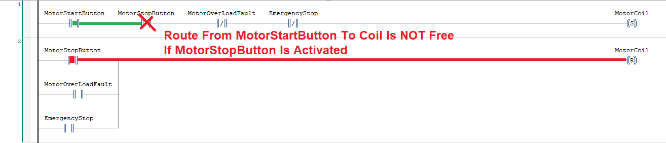
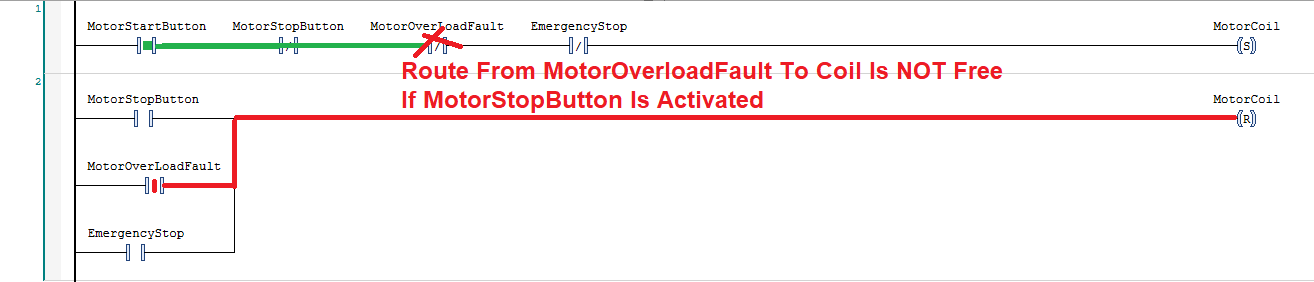
If you take a look at the way we have connected the signals leading to Motor Set Coil You will notice that the signals are connected in Serial. Meaning if one signal is not activated along the line, Then Motor Set Coil will never be active.
Reminder on How NO and NC work, when they have the same signal name:
If MotorStartButton NO is active, then MotorStartButton NC will be inactive. and vica versa.
© Copyright 2022 Advanced PLC. All rights reserved.